COOPERATION

AUTOMATIC BENDING

Fully automated sheet metal bending process as an alternative to traditional edge bending.

The first stage of automatic bending is to program the bending centre for the process. Once the appropriate material is given and the program is started, the bending is fully automatic until the desired shape is achieved. The finished product is fed through a feeder at the end of the production line.

We use automatic bending:

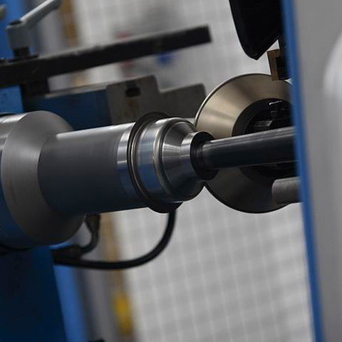
The Salvagnini p4xe – 3125 -automatic bending centre is designed for automatic sheet metal bending. Due to the automatic change-over, the machine has a high capacity. Salvagnini p4xe – 3125 also allows the production of customized solutions.

Automatic bending centre Salvagnini p4xe – 3125

THICKNESS 3 mm / black steel*
2 mm / chromonickel*
4 mm / aluminium*
LENGTH 330 – 3100 mm*
WIDTH 155 – 1524 mm*
MAX. DIAGONAL 3500 mm

*Dependent on the detail

COOPERATION

BENDING

It is a kind of material processing technology consisting of permanent change of curvature of a workpiece.

After programming the bending press, the operator places the sheet metal from which the element is formed on a special die. Pressing the stamp on the material causes the expected change of shape. In the case of the automatic process, the operator is replaced by a robot, which feeds and holds the material during bending and precisely places the product in the desired place.

We use edge bending:

The AMADA ASTRO 100 NT – cell is used for fully automatic bending. It is equipped with two robots and a servohydraulic bending press with a bending length of 3000 mm and maximum pressure of 100 tons.

The GASPARINI cell – is equipped with one robot. Maximum bending length is 1.3 m. The maximum pressure is 45 tons.

GASPARINI press brakesI – numerically programmed hydraulic presses with a maximum working length of 2.5 m and 1.6 m and a maximum pressure of 75 tons.

BYSTRONIC servo-electric presses – a press with a maximum pressure of 80 tons and a maximum bending length of 2 m.

AMADA ASTRO 100 NT for automatic bending with a servohydraulic press brake with a bending length of 3000 mm and a pressure of 100 tons (2 robots)
GASPARINI’S CELL Robotized with a bending length of 1.25 m and a pressure of 25 tons (1 robot)
GASPARINI PRESS BRAKES numerical, hydraulic:

with a maximum working length of 2.5 m and a maximum pressure of 75 t

with a maximum working length of 1.6 m and a maximum pressure of 40 t

with a maximum working length of 1.25 m and a maximum pressure of 25 t

BYSTRONIC SERVO PRESSES with a bend length of 2 m and a pressure of 80 tons (2 pieces)

COOPERATION

DEEP DRAWING

It is a technological process of plastic processing of metal sheets, which involves cutting and shaping small objects with regard to their width and length.

During the extrusion process, under the action of the stamp, the material is plasticized. The flat product is transformed into a three-dimensional coating, which cannot be spread on the surface.

We use it for pressing:

OMERA I hydraulic press -numerically controlled press with 250 tons of pressure. The maximum force of the pressing pad is 160 tons. The working area is 1000 x 800 mm.

Hydraulic press OMERA II – numerically controlled press with a maximum pressing force of 80 tons and a maximum pressing pad force of 30 tons. The working area is 600 x 450 mm.

PARAMETERS OMERA I OMERA II
MAXIMUM CONTACT FORCE 250 tonnes 80 tonnes
MAXIMUM CUSHION STRENGTH 160 tonnes 30 tonnes
WORK SURFACE 1000 x 800 mm 600 x 450 mm

COOPERATION

SPINNING

It is a type of sheet metal forming using tools, which utilize materials’ susceptibility to deformation.

The shaping of the sheet metal is carried out using special rollers for spinning. During the process there is no interruption of material continuity. As a result of material processing, the resulting product is a thin-walled rotary block.

We’re using it for fiction:

CNC ZENN 800 – numerically controlled spinning machine, enables spinning out elements with a maximum diameter of 800 mm. Maximum material thickness is 2 mm.

TECHNICAL DATA

MAXIMUM DIAMETER OF THE SPINDLE 800 mm
MAXIMUM MATERIAL THICKNESS 2 mm

COOPERATION

CUTTING

(laser)

Laser cutting is a technology for efficient cutting of materials, which consists in the generation of a large amount of energy by the laser radiation generator, focused on a small area.

LASER CUTTING

Laser beam cutting takes place over a very small, precisely defined area. The final products are characterized by a very high quality of the edges (without any additional processing) and, most importantly, 100% repeatability.

We use laser cutting:

The CO2 type laser gives the possibility to cut a variety of materials using a laser beam that is generated in the carbon dioxide medium. Cutting with a CO2 laser is characterized by a very small heat affected zone and a relatively narrow cutting gap. The fired elements are characterized by clean and perpendicular edges and small irregularities of the separation surface.

Fiber technology is a solution that has revolutionized the laser cutting market. Compared to CO2 technology, it is much faster and allows to achieve much better results, especially very dynamic and fast cutting of thin sheets. In addition, Fiber technology provides the highest dimensional accuracy by eliminating burrs and the absence of material overheating.

CO2 TYPE LASER

TYPE OF MATERIAL Black steel, stainless steel, galvanized sheet metal, aluminum,
THICKNESS OF CUT MATERIAL 0,5 mm – 5 mm
DIMENSIONS OF THE MATERIAL TO BE PROCESSED 1500 x 3000 mm
ACCURACY OF CUT +/- 0,1 mm

FIBER TECHNOLOGY

TYPE OF MATERIAL Black steel, stainless steel, galvanised sheet metal, aluminium, copper, brass
THICKNESS OF CUT MATERIAL 0,5 mm – 5 mm
DIMENSIONS OF THE MATERIAL TO BE PROCESSED 1500 x 3000 mm
ACCURACY OF CUT +/- 0,1 mm

COOPERATION

CUTTING

(3D laser)

3D cutting is a technology that enables the cutting of complex shapes in profiles and pipes.

3D LASER CUTTING

3D cutting consists in cutting out shapes of any size in the pattern. Depending on the technology, the process uses a plasma electric arc or laser beam.

For 3D cutting we use:

3D plasma pipe cutting machine – allows you to cut complicated shapes while maintaining high quality edges. The cutting process is carried out with a plasma arc which melts the material and then ejects it from the cutting slot.

1kW 3D laser with a space cutting robot – the device allows for precise cutting with clean and smooth edges. Cutting with 3D laser guarantees repeatability of shapes and dimensions with high efficiency.

TECHNICAL DATA

1kW 3D laser with space cutting robot

MAX. DIMENSIONS 600 x 600 x 800 mm*
MAX. BENDING THICKNESS 2 mm

*depending on the detail

3D plasma pipe cutting machine

MAX. WORKPIECE DIAMETER 600 mm
MAX. WORKPIECE LENGTH 1500 mm
MAX. CUTTING THICKNESS 2 mm

COOPERATION

CUTTING

Punching is the process of cutting out from sheet metal of any shape, by means of a tool called a punch, which is a reflection of the shape of the element being obtained.

The punching technology allows to shape simple elements and the most complex ones requiring high dimensional accuracy. The process allows to produce a large number of elements in a relatively short time.

WE USE TO CUTTING:

The AMADA AC 2510 NT– punching machine – has a brush table that prevents scratches. The punching force is up to 200 kN. The punching machine is characterized by high positioning and punching speeds, which translates directly into high performance.

The AMADA EM 3612 ZRT– punching machine is equipped with an automatic tool changer, which ensures maintenance-free and thus extremely efficient production, using several hundred tools. Thanks to the use of a brush table, the risk of sheet metal scratches is eliminated.

AMADA AC 2510 NT punching machine

TYPE OF MATERIAL Black steel, stainless steel, galvanized sheet metal etc.
THICKNESS OF CUT MATERIAL 0,5- 2 mm
DIMENSIONS OF THE MATERIAL TO BE PROCESSED 2500 x 1270 mm
POSITIONING ACCURACY +/- 0,1 mm

AMADA punching machine EM 3612 ZRT with automatic tool changer

TYPE OF MATERIAL Black steel, stainless steel, galvanized sheet metal etc.
THICKNESS OF CUT MATERIAL Max. 3 mm
DIMENSIONS OF THE MATERIAL TO BE PROCESSED 1500 x 3000 mm
POSITIONING ACCURACY +/- 0,1 mm

COOPERATION

QUALITY CONTROL

(scanner)

Quality control with a scanner is one of the fastest and most accurate ways to compare the recorded image of the actual semi-finished product to a standard.

The measurement is performed by scanning the real image with a CCD camera and comparing it to a CAD drawing. Any discrepancies between the pattern and the reality are displayed graphically on the device display a few seconds after the element is scanned.

We use quality control:

– The AMADA VQC-1220 optical measuring machine is designed for use in production. It is used to verify the correctness of the performed cutting or punching operation.

TECHNICAL DATA

AMADA VQC-1220 optical measuring machine

MEASURING SURFACE 3000 x 1250 mm ≠3 mm
ACCURACY OF MEASUREMENT 50 µm
DRZWICZKI, RAMKI DO DRZWICZEK I REGULATORA CIĄGU

Darco system

CHIMNEY CLEAN OUT DOORS AND CLEAN-OUTELEMENT MOUNTING FRAME

Chimney clean out doors – to cover the clean – out element of a chimney.
Clean out element mointing frame – mounting frame for doors and draught regulators RCW.

DRZWICZKI, RAMKI DO DRZWICZEK I REGULATORA CIĄGU

Chimney clean out doors are an aesthetical element covering the clean out element of a chimney system. Outer dimensions 205×225[mm] to a clean-out element channel of 125×185 [mm].

Clean out element mounting frame allows to mount the Darco-type cleaning doors as well as the RCW draught regulator in the Darco-type clean out element in a solid and durable way.

The clean out doors and clean out element mounting frame are made of chrome-nickel stainless steel. More information about dimensions and  technical drawings – see catalogue card in “Downlad” tab.

Darco system

CHIMNEY DAMPER KNOB; FLEXIBLE SHAFTS

Allows to connect the fireplace damper on an angular fireplace hood.

Damper knobs were designed for precise setting of chimney damper plate. Damper knob allows to set the damper plate in many positions, as well as prevents  it from exceeding the min/max positions (opened and closed). Its special construction prevents the knob from getting hot during operating. Knob is suitable to mounted with chimney dampers  of 8 mm and 10 mm shaft diameters. Removable front allows easy mounting and dismantling, for example during chimney hood finishing.

Available chimney dampers knobs:

  • Chimney damper knob – SZKZ-REG
  • Chimney damper knob light – SZKZ-REG-LIGHT
  • Rectangular damper knob – SZKZ-REG-KW
  • Round damper knob – SZKZ-REG-OK
  • Chimney damper … OS – on surface and under surface version

Compatibile with chimney dampers are:

Flexible shafts – flexible elements connecting the knob damper with axle damper – with rod which is attached to the damper. Using the flexible shaft is possible to provide the rotation with a knob on the axle damper. Due to its design allows the damper knob assembly anywhere in the building eaves of the fireplace.

Extension of flexible shaft – are a flexible extension od flexible shafts

Round and square joints – make it esier connect knob with chimney damper  a tan angle.

USAGE:

  • adjustment of the position of the chimney glass damper in the fireplace or stove

More information and technical drawings  of damper knobs and accesories – see the catalogue card in “Download” tab.