COOPERATION
SAND BLASTING
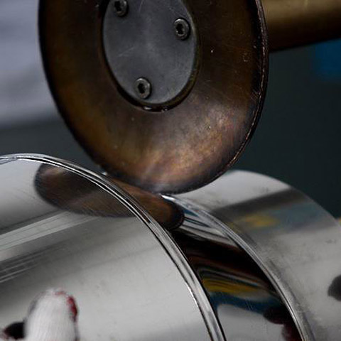
Merging of metal parts as a result of heating up and melting of the material at the point of joining. The source of heat is the welding arc. Welding takes place in a gas shielding, which has a direct impact on the efficiency and quality of welding.


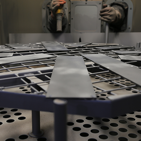
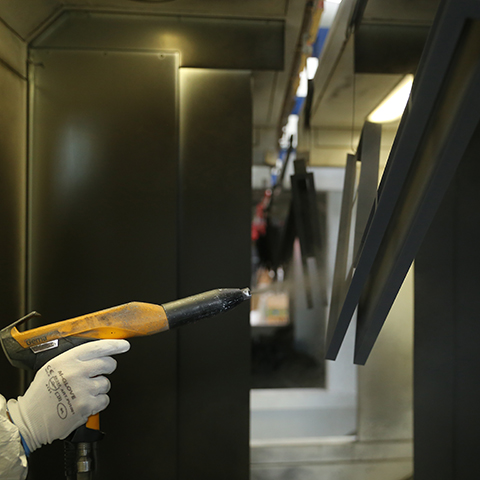
Sandblasting aims to remove contaminants and to standardize the surface structure. It takes place in a closed cabin. The operator, who is outside, sandblasts the elements with a special gun, from which an abrasive material (sand) is released in a compressed air stream. The result is a rough surface free of dirt and corrosion.
We use it for sandblasting:
Cabin dustless sanding machine PK 1TONA with dust extraction unit ZO 250 P is designed for sanding small and medium size elements. Thanks to adjustable pressure it is possible to obtain different speed of sand particles, and thus the desired roughness and possibility to sand any surface. The sandblasting machine is equipped with a dust extraction unit which filters out the dusts generated during sandblasting. This enables precise sandblasting of elements with the finest details.
Cabin dust-free sanding machine PK 1TONA with dust extraction unit ZO 250 P
| TYPE OF MACHINE | dust-free |
| WORKING PRESSURE | 3-6 bar |
| TYPE OF TABLE | Rotary |
| MAXIMUM WORKPIECE DIMENSIONS | To be agreed |


")
")