COOPERATION

SAND BLASTING

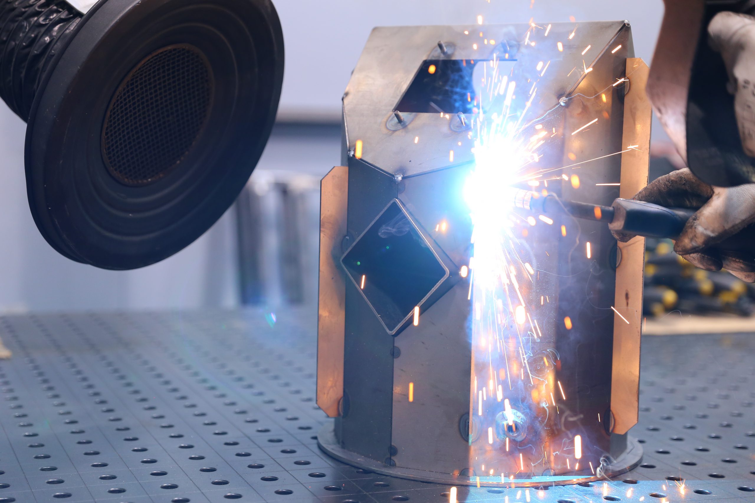
Merging of metal parts as a result of heating up and melting of the material at the point of joining. The source of heat is the welding arc. Welding takes place in a gas shielding, which has a direct impact on the efficiency and quality of welding.
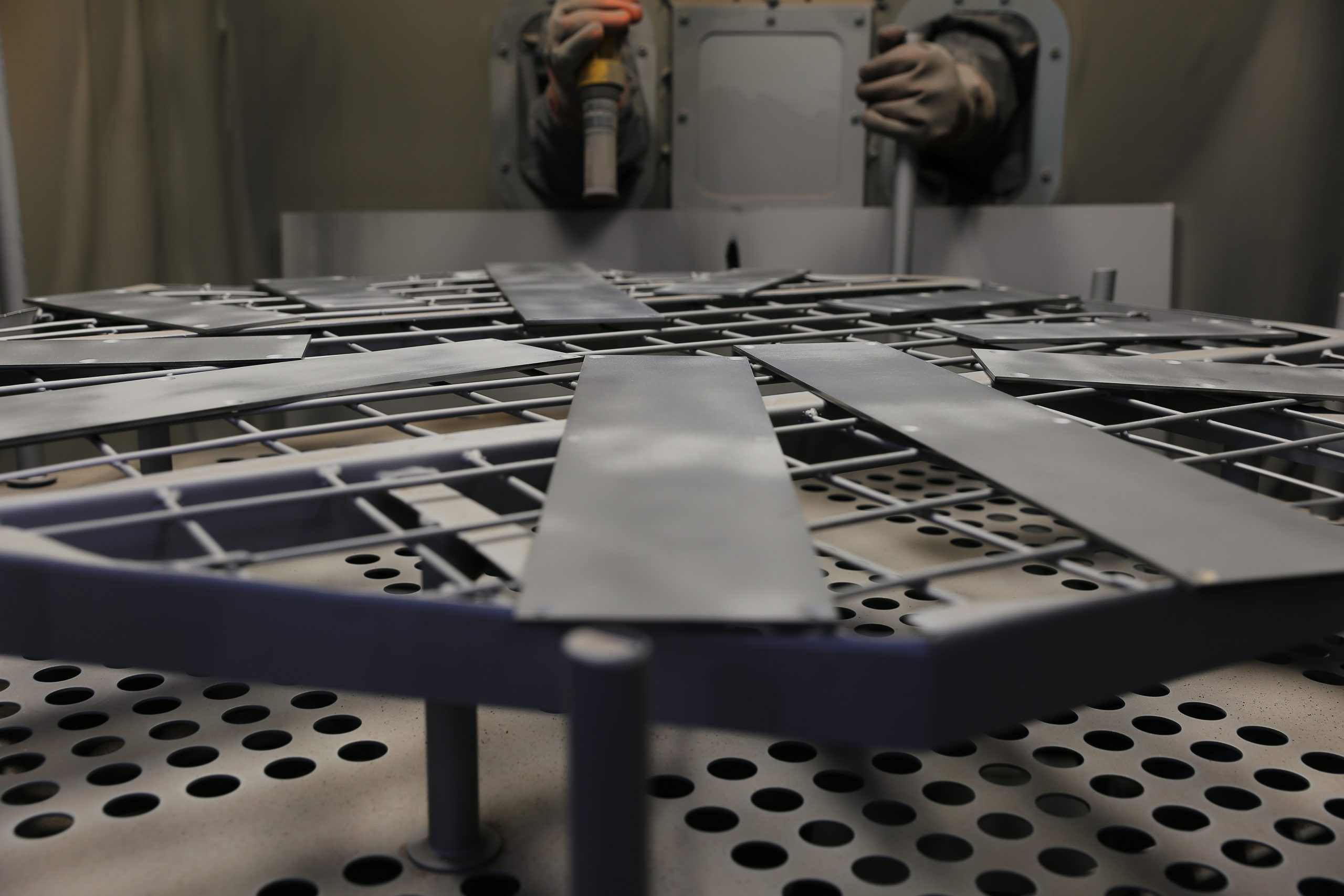
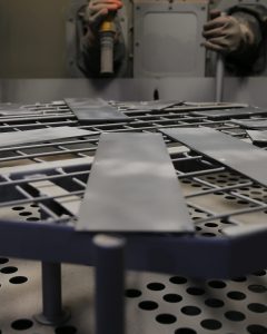
Sandblasting aims to remove contaminants and to standardize the surface structure. It takes place in a closed cabin. The operator, who is outside, sandblasts the elements with a special gun, from which an abrasive material (sand) is released in a compressed air stream. The result is a rough surface free of dirt and corrosion.

We use it for sandblasting:

Cabin dustless sanding machine PK 1TONA with dust extraction unit ZO 250 P is designed for sanding small and medium size elements. Thanks to adjustable pressure it is possible to obtain different speed of sand particles, and thus the desired roughness and possibility to sand any surface. The sandblasting machine is equipped with a dust extraction unit which filters out the dusts generated during sandblasting. This enables precise sandblasting of elements with the finest details.

Cabin dust-free sanding machine PK 1TONA with dust extraction unit ZO 250 P

TYPE OF MACHINE dust-free
WORKING PRESSURE 3-6 bar
TYPE OF TABLE Rotary
MAXIMUM WORKPIECE DIMENSIONS To be agreed

COOPERATION

PHOSPHATE TREATMENT

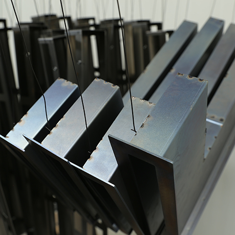
The process of chemical production of a protective coating on metal surfaces in order to protect them from corrosion and high temperatures. Thanks to the reduced friction coefficient, the coating is an excellent primer for paints and varnishes.

The elements subjected to the phosphating process are placed in a special container in which they are immersed in hot phosphate and phosphoric acid solutions. After being cleared of any deposits, the elements are transported for 10 minutes to an oven preheated to 110 °C.

We use it to phosphate:

A bathtub of phosphate and phosphoric acid solution and a bathtub of clean water, which have aeration, so that the solution reaches every place and all impurities are removed from the elements cleaned in water. The coating prepared in this way constitutes an ideal, anti-corrosion surface ready for further processing.

DIMENSIONS OF THE HOPPERS 1400 x 800 x 1000
BATH TYPE (COATING) Hot phosphate and phosphoric acid solutions
TYPE OF BATH (RINSING) Clean water
OVEN TEMPERATURE (DRYING) 110 °C
DRYING TIME 10 min

COOPERATION

AUTOMATIC POWDER COATING

The process of automatically applying electrified powder paint particles to the metal surface. The powder layer is maintained on the surface due to electrostatic forces. The electrification of the particles takes place by electrostatic spraying (high voltage method).

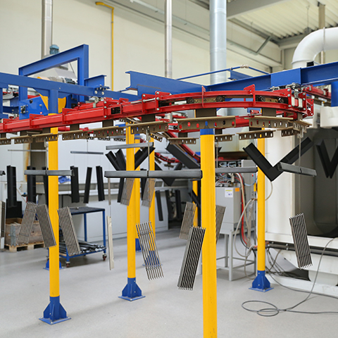
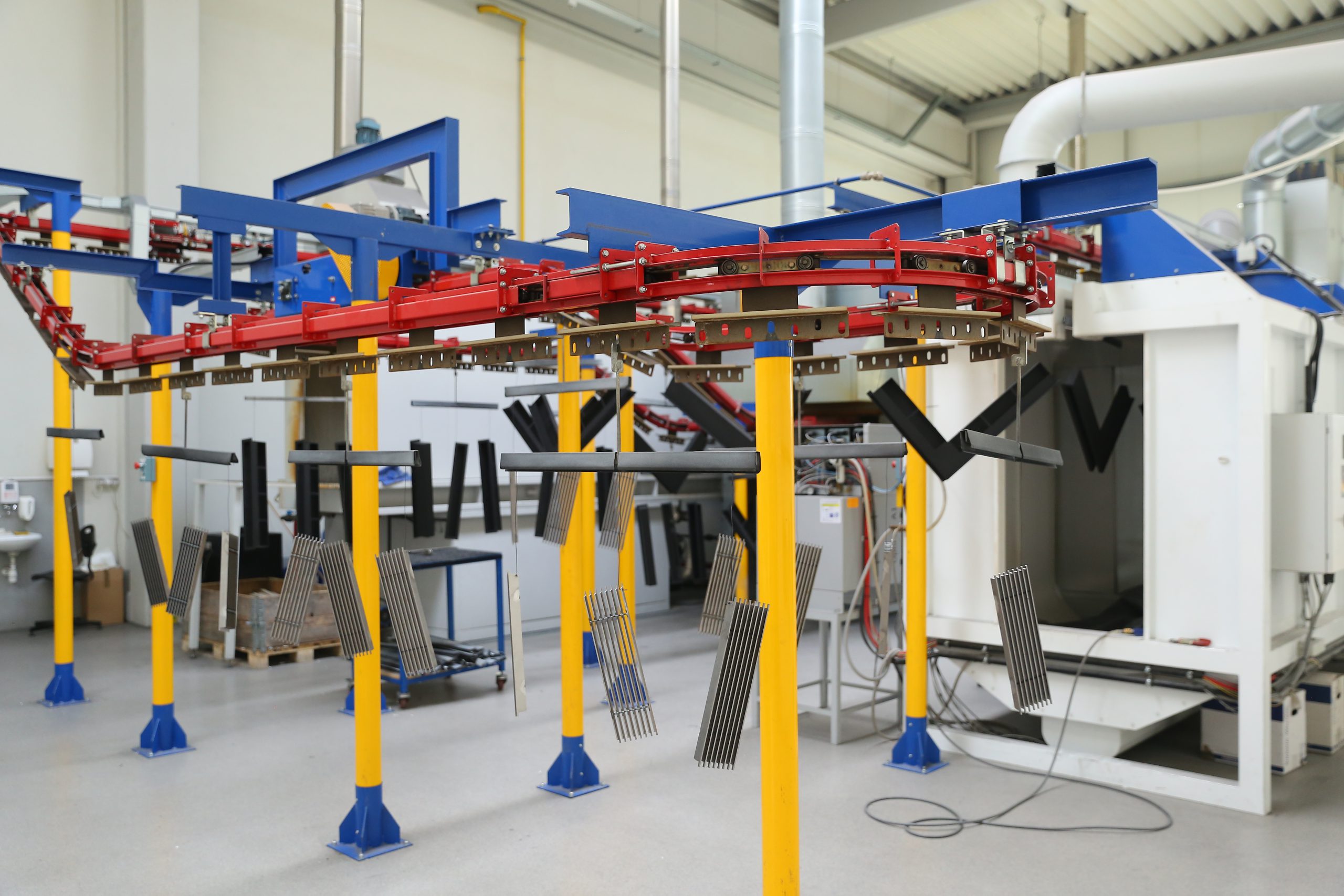
The process cycle in the paint shop consists of the following stages: loading of the parts, zirconium conversion, washing in ordinary water, rinsing in demineralised water, drying, painting, polymerisation, cooling and unloading of the parts. The use of automatic methods used in the painting process guarantees high quality and durability of the coating while maintaining an aesthetic appearance.

For automatic powder coating we use:

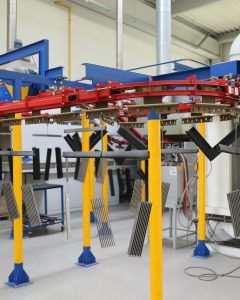
Automatic Painting House EURO 90 – is a painting line designed for painting metal elements with thermosetting powder paints. The paint shop consists of a surface preparation tunnel, drying oven, paint booth, firing furnace and a monorail conveyor. Finished products are characterized by high mechanical and corrosion resistance and obtain the desired gloss and shade. The whole process is automated.

Automatic paint shop EURO 90

APPLICATION OF POWDER VARNISH Automatic electrostatic shower
MAXIMUM DIMENSIONS OF PAINTED ELEMENTS 1000 x 600 x 1000
SURFACE PREPARATION Zirconium conversion
MAXIMUM LINE SPEED 1m/min
CONVEYOR TYPE Monorotation
POWDER PAINT PARTICLE SIZE from 20 to 100 μm.

COOPERATION

POWDER COATING

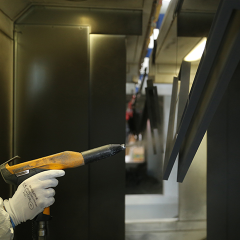
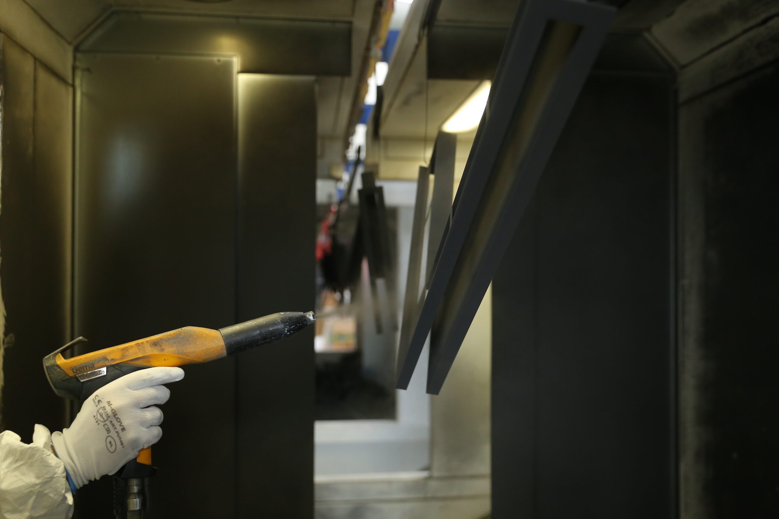
Manual powder coating is a process of applying electrified powder paint particles to the metal surface. The powder layer adheres to the metal surface due to electrostatic forces. The electrification of the particles is achieved using the voltage method and is carried out by electrostatic spraying.

The paint shop’s technological cycle consists of the following stages: loading of the details, preparation of the surface by bathing in hot phosphate and phosphoric acid solution together with rinsing in clean water and drying in an oven, painting, polymerization, cooling and unloading of the details.

For manual powder coating we use:

Manual paint shop – is designed for painting metal parts with high temperature curing powder paints. The paint shop consists of bathtubs for surface preparation, paint booth and baking oven. After hardening, the coating is characterized by above-average mechanical resistance and thanks to the phosphate coating, high corrosion resistance. Activities in the process of manual powder coating are performed by employees.

APPLICATION OF POWDER VARNISH Manual
MAXIMUM DIMENSIONS OF PAINTED ELEMENTS 1400 x 1000 x 800 mm
SURFACE PREPARATION Bathing in a hot solution of phosphates and phosphoric acid
POWDER PAINT PARTICLE SIZE from 20 to 100 μm.

COOPERATION

AUTOMATIC WELDING

Fusion of metal parts as a result of heating and melting of material at the point of joining by means of an automatic welding robot. Automatic welding can be carried out with a fusible electrode or tungsten electrode.

The automatic welding process starts with the creation of a control program and a suitable holder for mounting the welded element on the table. After programming the robot, the operator places the welded element in the welding cell and closes the welding cell door. The robot joins the elements together with great accuracy.

WELDING METHOD MIG, TIG
SHIELD GAS Argon
MAXIMUM WORKPIECE DIMENSIONS 800 x 800 x 800*


*depending on the detail

COOPERATION

WELDING

Merging of metal parts as a result of heating up and melting of the material at the point of joining. The source of heat is the welding arc. Welding takes place in a gas shielding, which has a direct impact on the efficiency and quality of welding.

MIG/MAG (Metal Inert Gas / Metal Active Gas) – welding is a method of welding with a consumable electrode in an inert gas shield (MIG 131) or in an active gas shield (MAG 135), in which an electric arc glows between the electrode (as a wire) and the material being welded. This method is designed for the fusion of most materials (the appropriate electrode wire and shielding gas must be chosen).

TIG welding (Tungsten Inert Gas) – is a method of welding with an inert gas shielded tungsten electrode (argon, helium) in which an electric arc glows between the electrode and the material being welded. This method is designed for welding all types of steel (especially high-alloy steels and non-ferrous metals).

TIG welding

WELDING METHOD TIG
CURRENT ADJUSTMENT RANGE 4- 300 A
SHIELD GAS Argon
ELECTRODE DIAMETER 1,6- 3,2 mm

MIG/MAG welding

WELDING METHOD MIG/ MAG
SCOPE OF INTENSITY CONTROL 50- 315 A
SHIELD GAS Argon/ Corgon 10
WELDING WIRE DIAMETER 0,6- 1,2 mm

Turntable

TILT ANGLE OF THE TABLE 0- 90°
DRIVE Gearmotor – helical-worm gearbox
PURPOSE Oval swivels
DIAMETER OF WELDED PARTS 140- 370 mm

COOPERATION

SPOT WELDING

Merging of metal elements involves heating up the surface and then squeezing it. Under the influence of pressure of the surfaces in the plastic state, they are permanently joined. Depending on the welding method, first pressure is applied and then welding or vice versa.

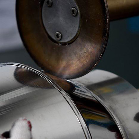
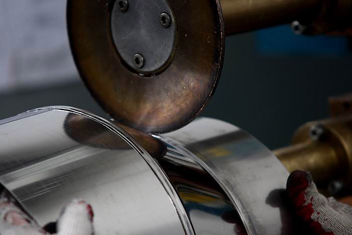
Linear welding – the joining of elements is carried out on welders equipped with disc electrodes. The connection is obtained along the line, which consists of two overlapping spot welds. The welding speed is in the range of 0.5 -3 m/min. This technology works well for joining carbon steels, alloy steels and non-ferrous metals.

Spot welding – joining elements in separate places (points). It consists in pressing the elements to each other by the welding electrodes, which heat the element in the place of joining, creating a liquid core of the weld. After the nucleus of the weld becomes solid, a uniform joint is formed.

We use it for welding:

Resistance spot welding machine with vertical pressure ASPA ZPb – 6 – table welding machine, designed for spot welding of small parts. It is equipped with a vertical pneumatic pressure system, which allows to obtain high quality welds. The small overhang and arm span makes the device obtain a significant welding current.

CEMSA MRT 450 70 AP/VENT linear welding machine – designed for cross-over linear welding. It is ideal for welding ventilation ducts, smoke ducts, various types of tanks, etc. It enables welding of large diameters. It has an adjustment of the rotational speed of the disc electrodes and clamping force. Designed for continuous or “overlap” welding.

Resistance spot welding machine with vertical pressure ASPA ZPb- 6

MAXIMUM THICKNESS OF THE MATERIAL TO BE WELDED 0.5-2 mm (depending on the material)
ELECTRODE PRESSURE 1400 N
TYPE OF PRESSURE pneumatic
MAXIMUM SECONDARY SHORT CIRCUIT CURRENT 14000 A
COOLING Water

Linear welding machine CEMSA MRT 450 70 AP/VENT

MAXIMUM THICKNESS OF THE WELDED ELEMENT depending on the material
TYPE OF CURRENT alternating or medium frequency direct current
TYPE OF PRESSURE pneumatic
MAXIMUM POWER 50- 500 kVAA
WELDING SPEED 0,5-3 m/ min

COOPERATION

RIVERING

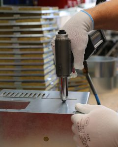
It is a kind of joining elements with rivets. There is no inherent stress in riveting, which makes it possible to connect elements made of different materials.

Rivet fixing – in a drilled hole in the elements to be joined, a suitable length of rivet is mounted. The protruding mandrel is placed in the riveting die, which causes the rivet to swell, creating a cap that prevents the rivet from sliding and escaping from the hole, thus creating an inseparable connection of the elements.

Rivet nuts mounting – the mounting consists of screwing in the threaded pin from the flange side. Then the riveted nut is placed in the hole and pressed down with a riveting iron. By the return movement of the shank, the material is cracked. The mandrel is then removed by unscrewing.

For riveting we use:

Pneumatic riveting machine for rivets – this device is designed for heavy industrial work. Thanks to its replaceable tip, it enables the assembly of rivets with a diameter of 2.4 – 6.4 mm. The riveting machine is equipped with a system for sucking off the remains of broken rivets. The appropriate force allows one rivet to break off each rivet in one cycle.

Pneumatic riveting machine for rivet nuts – a device designed for mounting rivet nuts of any material. Its biggest advantages are: wide range of applications and simple and quick shank replacement, which translates into high performance.

TECHNICAL DATA

Pneumatic riveting machine

RIVET DIAMETER 2,4- 6,4 mm
RIVET MATERIAL Aluminium, stainless steel, copper, steel
WORKING PRESSURE 5-7 bar

Pneumatic riveting machine for rivet nuts

DIAMETER OF THE RIVET NUT M3- M12
RIVET MATERIAL Steel, aluminium, stainless steel
WORKING PRESSURE 6,3 bar

COOPERATION

LATHES

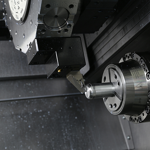
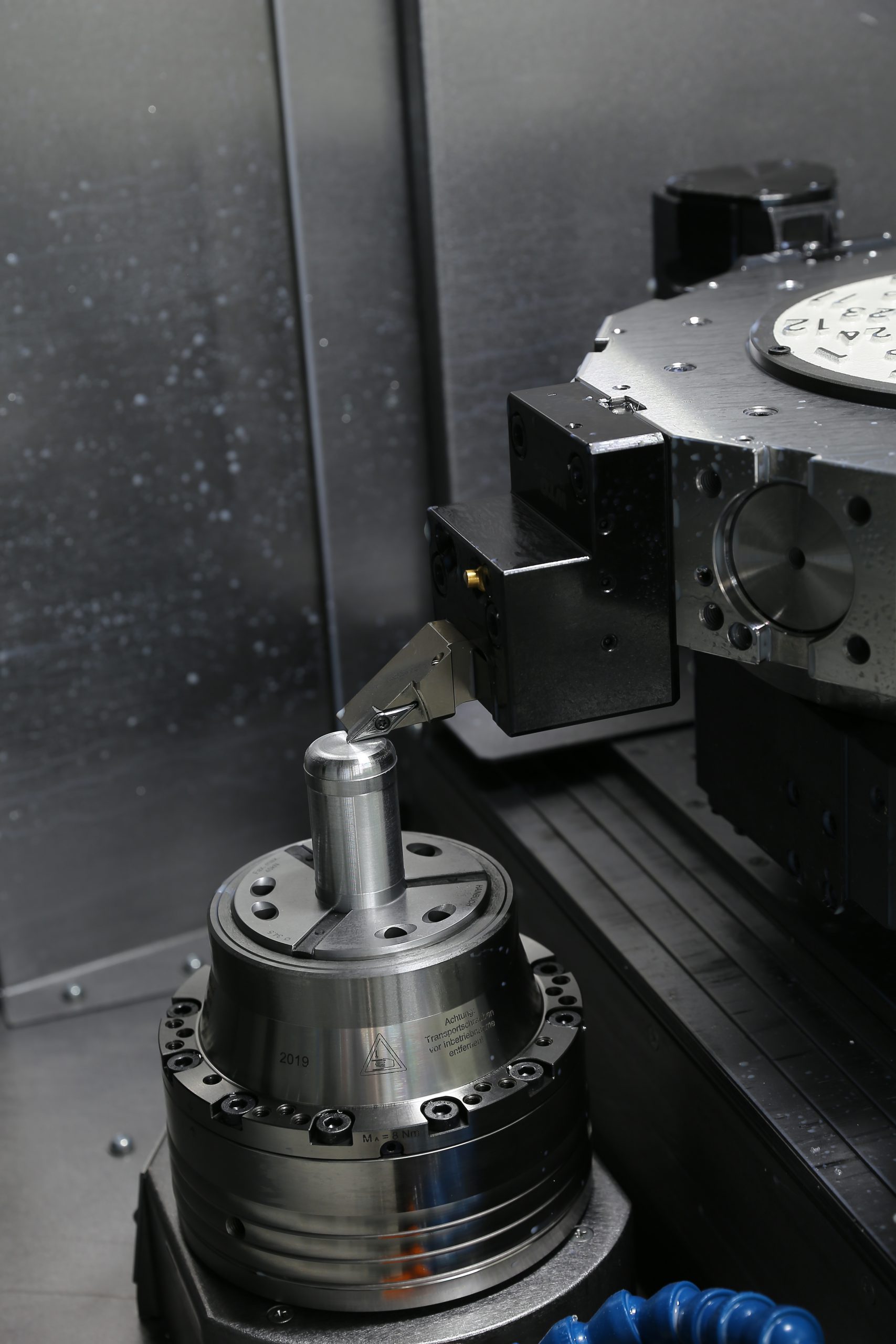
It is a machining method in which the rotary movement is performed by the workpiece, while the feed movement is performed by a special tool – a turning knife.

Turning is the mutual movement of the tool and the workpiece. The workpiece, driven by the lathe’s spindle, performs a rotary motion. The tool performs an auxiliary feed movement. These movements overlap and add up. In the end, they achieve a previously planned machining target by turning.

We use it to roll:

CNC lathe – is a combination of conventional and numerical machine. This type of machine produces complex profiles in a constant quality, even with more pieces. It is characterized by high dynamics of working movements, positioning accuracy and excellent rigidity.

CNC lathe machines– machines designed for medium and large-scale production. They are perfect for making elements with complex shapes and those that require special precision. The objects processed in them are characterized by high quality of workmanship.

TECHNICAL DATA

CNC LATHE maximum rolling diameter: Ø 300
Spindle clearance: Ø52
CNC LATHES Maximum rolling diameter: Ø 38

COOPERATION

MILLING

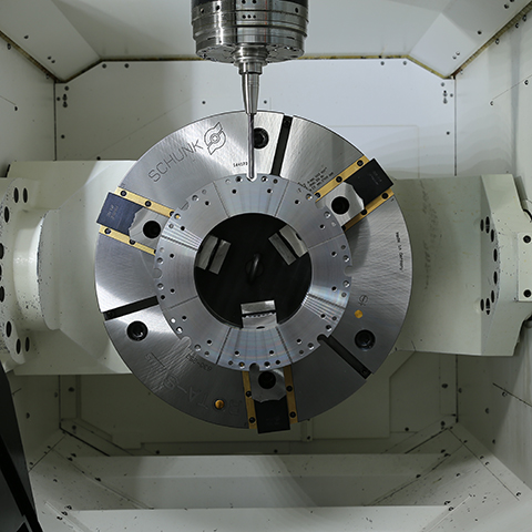
It is a type of machining in which the rotary movement is performed by the tool, while the feed movement (depending on the design of the machine tool) can be performed by the tool or workpiece.

Milling is the separation of the metal layer by means of a multi-cutter cutter. The milling cutter performs a rotary motion, while the feed motion is performed by the workpiece (sometimes also the tool). During the cutting process, the edges of the milling cutter do not work all at once, only their specific part.

For milling we use:

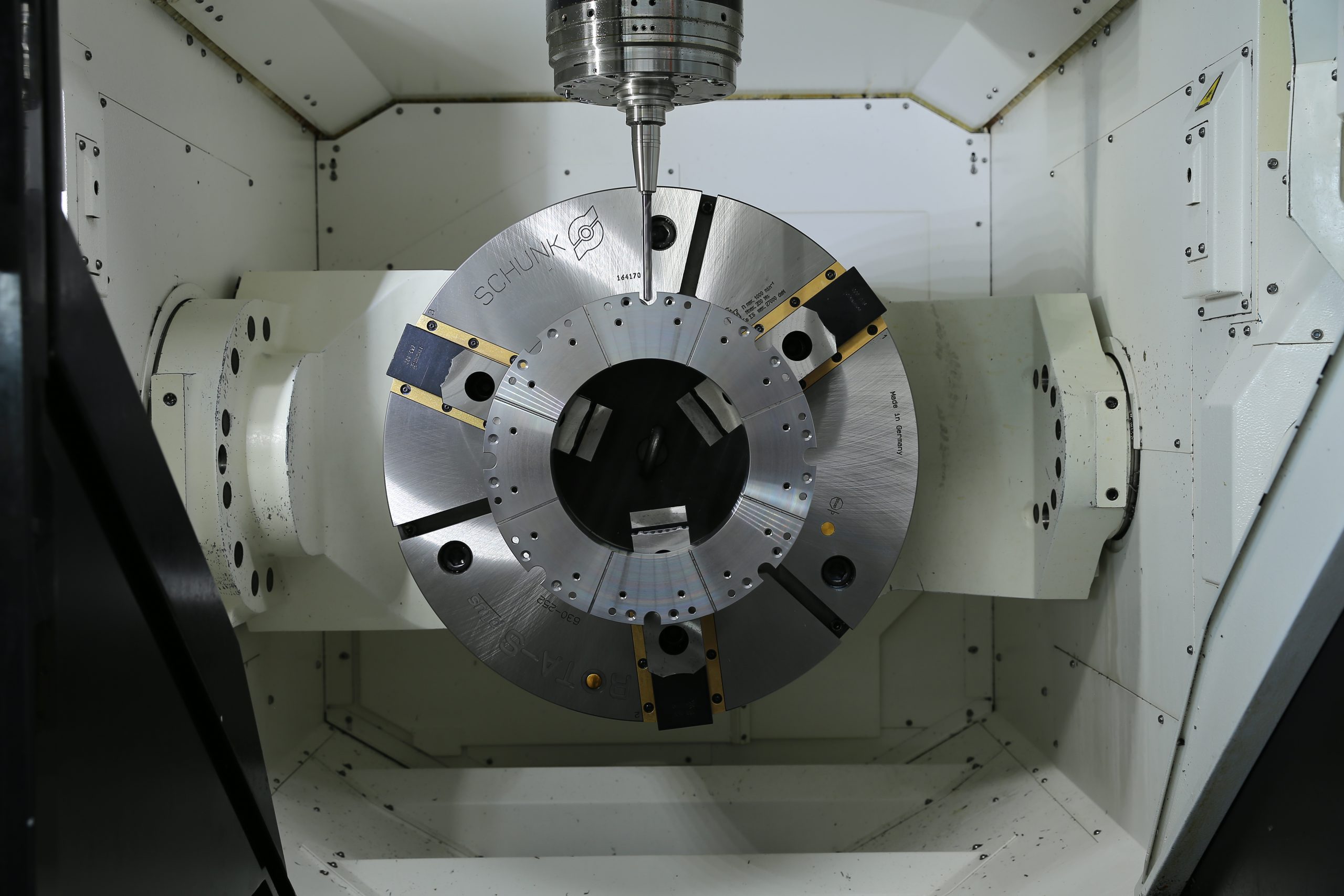
The MAZAK VARIAXIS i-700T 5-axis machining centre – is a vertical machining centre designed for multi-purpose machining with simultaneous 5-axis control. It is characterized by high efficiency in high-speed and fine machining.

MAXIMUM DIAMETER OF THE WORKPIECE 850 mm
MAXIMUM WORKPIECE HEIGHT 500 mm
MAXIMUM MASS OF THE WORKPIECE 600 kg